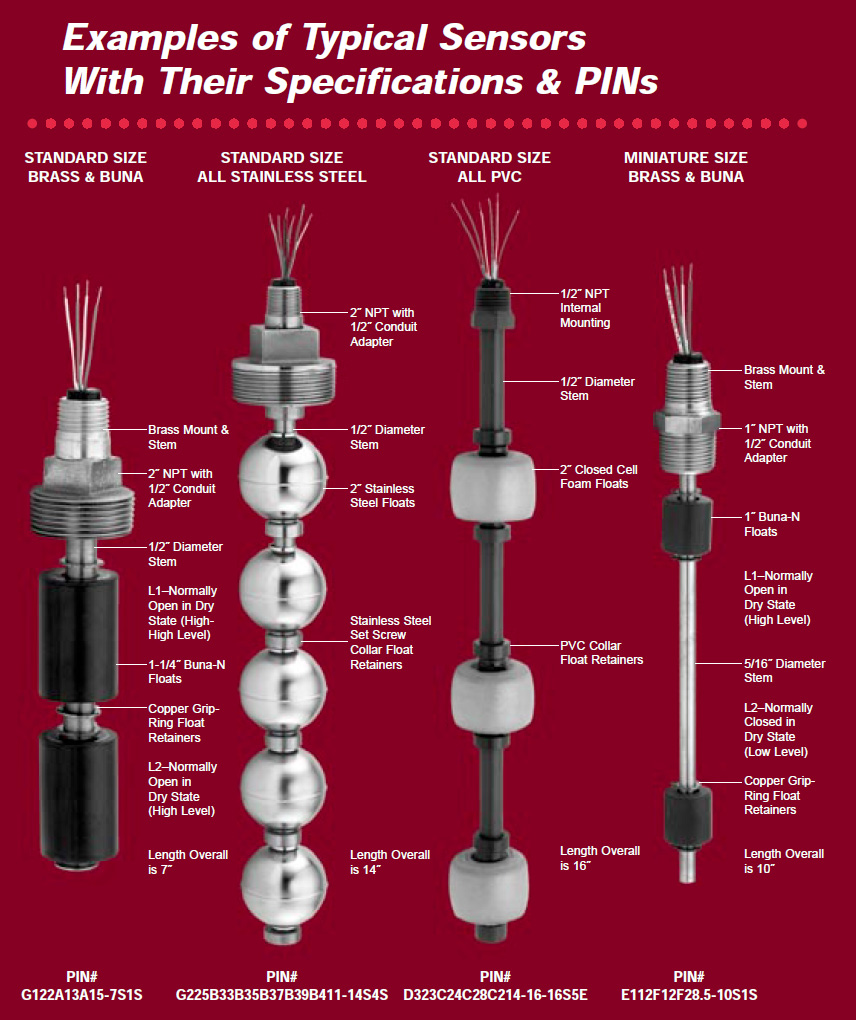
Multi-Level Sensors are a single tubular sensor that may contain multiple discreet sealed contacts. This design enables you to perform several functions with one piece of equipment. They install easily and quickly with a variety of mounting types.
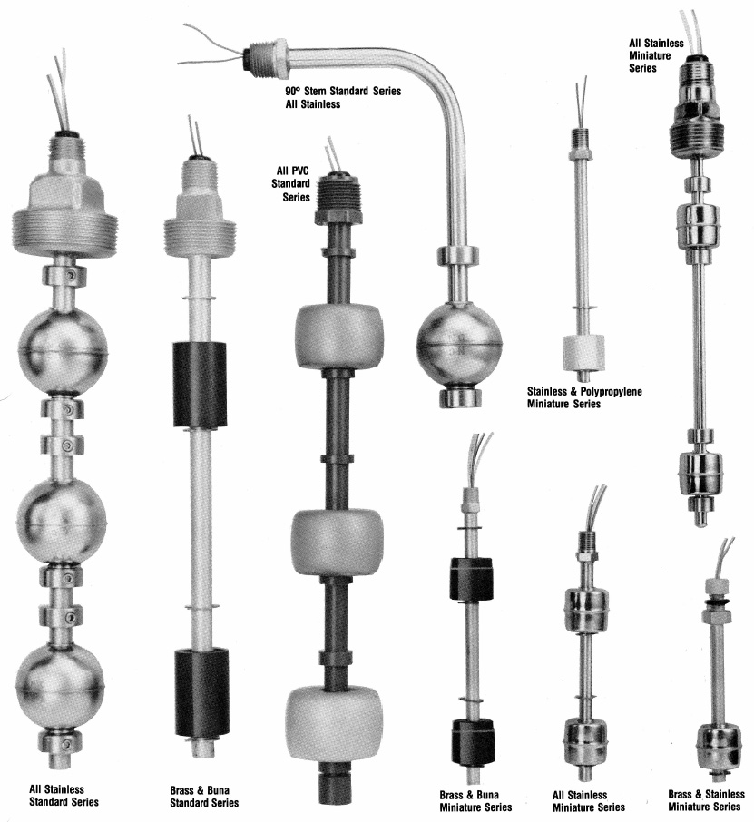
Nationals’ multi-level sensors are available in Stainless Steel, Brass & Buna, PVC and Polypropylene.
Tough
Employing low-mass hermetically sealed magnetic contacts, MLS (multi-level sensors) are not usually affected by vibration or shock, and therefore are used in applications where engines, generators, and other types of heavy machinery operate.
This includes general marine and industrial applications. Generator Sets, Fuel Cells, Compressors, Lubrication Systems, Fuel Storage, and Hydraulic Tanks, are just some of the areas these sensors have been used successfully.
Versatile
When you need to start or stop pumps, open or close solenoid valves, provide spill prevention with High Alarm contacts, prevent fuel or lubrication run out with Low Alarm contacts, startup or prevent operations with a level operated interlocking contact, even detect higher or lower than desired temperatures in these liquids, (such as hydraulic fluid) MLS Sensors can handle the requirement cost effectively.
Reliable
MLS sensors have been constructed as small as a drinking straw and up to fifteen feet in length in various materials. Miniature floats accommodate smaller volume tanks, while larger heavier floats are used in viscous liquids or liquids containing particulate. Because they are built to work under conditions that are specified, most MLS sensors provide very long service life, in many cases 12-18 years have been reported in Marine applications! No “off the shelf general purpose control” can provide this type of service length or reliability.
Specifications
Use the “menu” in our DESIGNERS GUIDE to become familiar with the features available for your sensor. Then call our 800# to discuss your application with one of our sales engineers. Let us show you how easy this process can be. With our unique modular engineering and construction techniques, sensors can be specified, manufactured and shipped with incredibly short lead times.

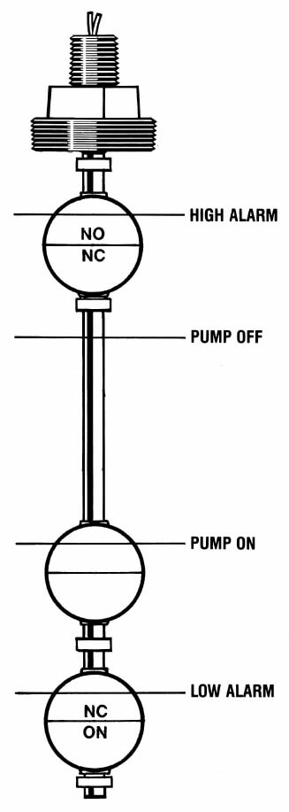
A popular configuration is shown above where there is need for controlling a pumping operation while providing high and low alarm points in case of pump failure.
Quality, Reliability, Simplicity of Operation… Direct Level Magnetic Sensors Custom Built To your Exact Specifications
When you must provide a complete cycle, or function to a process, rather than a simple contact, a multi-level sensor is your simplest and most cost effective solution. Essentially it is a probe with multiple magnetic sensors housed inside, with switch logic and dimensions to suit a specific job, such as automatically refilling a day-tank with fuel. Many such jobs can be critical, and it is easy to add redundant levels for control backup, or independent alarm contacts. A low-level alarm for a day-tank with power totally isolated from the control contacts would be a good example. Before you begin, you should gather information on temperature, pressure, and the liquid’s characteristics. Is it still or turbulent? What is the viscosity? Is particulate present? You also need to know what the “load” for the sensor will be. Is there an existing fitting that can be used, or does one need to be installed?
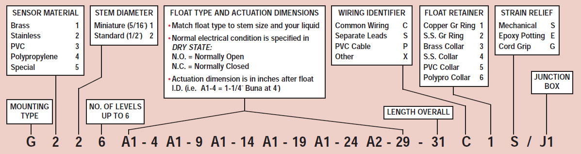
How to specify the perfect multi-level sensor for your system
 From the Mounting Type charts on the next page, select a PIN ID code letter (i.e. G).
- From the chart below select an appropriate Sensor Material (i.e. 2 for SS)
- From the chart below select a Stem Diameter allowed for the fitting and float size of your tank (i.e. 2 for Standard 1/2″ Size).
- Decide the Number of Levels needed (i.e. 6).
- Float selection comes next. (In our example, since we have selected Standard Size, we pick from the choices in the Standard Float Series.) Floats come “packaged” with reeds: types SPST, SPDT, 10-100VA; Normally Open or Normally Closed contacts. (i.e. A2-8 means a 15W reed Normally Closed, 8″ down from mount. CAUTION: Floats are designed to fit through female fittings of a stated size, not pipe of that size! (i.e. 2″ SS floats will fit through a 2″ NPT half-coupling, but not through a 2″ NPT Pipe Nipple.) Also, if a sensor is to be mounted up-side down on the bottom of a tank, be sure to reverse the PIN’s float identifying series to obtain the desired electrical condition in the dry state.
- For Length Overall, refer to the Limitations Chart below, which indicates minimum and maximum dimension limits for a sensor.
- Wiring Identifiers: From the chart below pick the letter representing the wiring you prefer. However, a very complex sensor may only be available with “common” wiring.
- Float Retainers: Specify “grip-ring” retainers for lightweight or miniature floats or static, nonturbulent applications. They provide good service in fuel or lubricant use. Collar type retainers should be specified for stainless floats; turbulence in tanks, portable or transportable applications and water based fluids.
- Strain Reliefs: Mechanical for standard duty. Epoxy potted for tamper resistance, and some protection against light condensation or moisture. Cord Grips in conjunction with cable provide liquid-tight capability from outside as well as inside the tank (immersible).
- Junction Boxes: Nema 4X provides protection from dirt, dust, bodily contact and water-tightness as in washdown situations. Nema 7-9 are for hazardous areas as defined by electrical codes. Both may contain terminal strips standard, and can be ordered with small control relays.
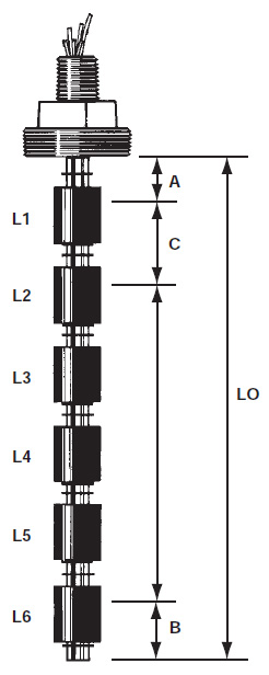
Sensor Dimensional Limitations
| DIMENSIONS (IN DIAGRAM AT LEFT) | STAND. SERIES | MINI. SERIES |
| A = Mount to first level–Minimum | 1-1/2″ | 3/4″ |
| C = Space between levels–Minimum | 3″ | 2″ |
| B = Bottom level to stem end–Minimum | 2″ | 1-1/2″ |
| LO = Sensor length overall–Maximum | 12′ | 6′ |

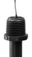
External Mounting

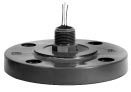
Internal Mounting
Specification Codes for your Custom Pin (Product Identification Number)
Mounting Types
 |
|||
EXTERNAL MOUNT W/O CONDUIT ADAPTER |
|||
| NPT SIZE | PIN ID | AVAILABLE MATERIALS | STEM SIZE |
| 1/2″ | U | BR, SS | 5/16″ Only |
| 3/4″ | J | BR, SS, PVC | 5/16″ Only |
| 1″ | M | BR, SS, PVC | 5/16″ Only |
| 1-1/4″ | K | BR, SS, PVC | 5/16″ or 1/2″ |
| 1-1/2″ | AZ | BR, SS, PVC | 5/16″ or 1/2″ |
| 2″ | W | BR, SS, PVC, PP | 5/16″ or 1/2″ |
| 3″ | DD | BR, SS, PVC | 1/2″ Only |
| 4″ | BA | BR, SS, PVC | 1/2″ Only |
 |
|||
EXTERNAL MOUNT W/ CONDUIT ADAPTER |
|||
| NPT SIZE | PIN ID | AVAILABLE MATERIALS | STEM SIZE |
| 1/2″ | AA | BR, SS | 5/16″ Only |
| 3/4″ | BB | BR, SS, PVC | 5/16″ Only |
| 1″ | E | BR, SS, PVC | 5/16″ Only |
| 1-1/4″ | F | BR, SS, PVC | 5/16″ or 1/2″ |
| 1-1/2″ | MM | BR, SS, PVC | 5/16″ or 1/2″ |
| 2″ | G | BR, SS, PVC, PP | 5/16″ or 1/2″ |
| 3″ | CC | BR, SS, PVC | 1/2″ Only |
| 4″ | ZZ | BR, SS, PVC | 1/2″ Only |
 |
|||
INTERNAL MOUNT |
|||
| NPT SIZE | PIN ID | AVAILABLE MATERIALS | STEM SIZE |
| 1/8″ | A | BR, SS | 5/16″ Only |
| 1/4″ | B | BR, SS | 5/16″ or 1/2″ |
| 3/8″ | C | BR, SS | 5/16″ or 1/2″ |
| 1/2″ | D | BR, SS, PVC | 5/16″ or 1/2″ |
| 3/4″ | HH | BR, SS, PVC | 5/16″ or 1/2″ |
| 1″ | AK | BR, SS, PVC | 5/16″ or 1/2″ |
 |
|||
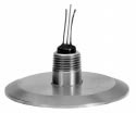
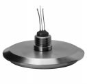
ANSI FLANGE W/ CONDUIT ADAPTER |
|||
| SIZE | PIN ID | AVAILABLE MATERIALS | STEM SIZE |
| 1.5″ | AO | SS/CARB/PVC/PP | 5/16″ or 1/2″ |
| 2″ | Z | SS/CARB/PVC/PP | 5/16″ or 1/2″ |
| 3″ | H | SS/CARB/PVC/PP | 5/16″ or 1/2″ |
| 4″ | I | SS/CARB/PVC/PP | 5/16″ or 1/2″ |
 |
|||
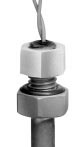
INTERNAL MOUNTING W/ O-RING & NUT |
|||
| THRD. SIZE | PIN ID | AVAILABLE MATERIALS | STEM SIZE |
| 3/8-16 | V | SS, PVC | 5/16″ Only |
| 7/16-20 | X | SS, PVC | 5/16″ Only |
| 5/8-18 | EE | SS, PVC | 5/16″ or 1/2″ |
 |
|||
TRI-CLOVER CAP W/ CONDUIT ADAPTER |
|||
| SIZE | PIN ID | AVAILABLE MATERIALS | STEM SIZE |
| 1.5″ | PP | SS | 5/16″ or 1/2″ |
| 2″ | P | SS | 5/16″ or 1/2″ |
| 2.5″ | T | SS | 5/16″ or 1/2″ |
| 3″ | Q | SS | 5/16″ or 1/2″ |
| 4″ | AP | SS | 5/16″ or 1/2″ |
 |
|||
I-LINE CAP W/ CONDUIT ADAPTER |
|||
| SIZE | PIN ID | AVAILABLE MATERIALS | STEM SIZE |
| 2″ | AR | SS | 5/16″ or 1/2″ |
| 2.5″ | AQ | SS | 5/16″ or 1/2″ |
| 3″ | KK | SS | 5/16″ or 1/2″ |
 |
|||
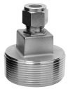
EXTERNAL MOUNT ‘SLIP-FIT’ TYPE COMPRESSION FITTING |
|||
| NPT SIZE | PIN ID | AVAILABLE MATERIALS | STEM SIZE |
| 1″ | FF | BR, SS | 5/16″ or 1/2″ |
| 1-1/4″ | O | BR, SS | 5/16″ or 1/2″ |
| 1-1/2″ | AY | BR, SS | 5/16″ or 1/2″ |
| 2″ | GG | BR, SS | 5/16″ or 1/2″ |
 |
||
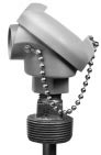
JUNCTION BOX ACCESSORYAvailable on all mounts with conduit adapters |
||
| PIN ID | AVAILABLE MATERIALS | STEM SIZE |
| J1 | DELRIN | 4, 6, 13 |
| J2 | IRON (X-Proof) | 7, 9, 13 |
| J3 | ALUMINUM | 4, 13 |
Float Types – Standard Series
 |
|||
1-1/4″ BUNA-N |
|||
|
|||
| PIN ID | DESCRIPTION | ||
| A1- | 15 Watt N.O. | ||
| A2- | 15 Watt N.C. | ||
| A3- | 100 Watt N.O. | ||
| A4- | 100 Watt N.C. | ||
| A5- | 20 Watt SPDT | ||
| X6- | 15 Watt–No Float | ||
| X7- | 100 Watt–No Float | ||
| X8- | 20 Watt SPDT–No Float | ||
 |
|||
2″ POLYPROPYLENE |
|||
|
|||
| PIN ID | DESCRIPTION | ||
| AD1- | 15 Watt N.O. | ||
| AD2- | 15 Watt N.C. | ||
| AD3- | 100 Watt N.O. | ||
| AD4- | 100 Watt N.C. | ||
| AD5- | 20 Watt SPDT | ||
| X6- | 15 Watt–No Float | ||
| X7- | 100 Watt–No Float | ||
| X8- | 20 Watt SPDT–No Float | ||
 |
|||
2″ 316 STAINLESS STEEL |
|||
|
|||
| PIN ID | DESCRIPTION | ||
| B1- | 15 Watt N.O. | ||
| B2- | 15 Watt N.C. | ||
| B3- | 100 Watt N.O. | ||
| B4- | 100 Watt N.C. | ||
| B5- | 20 Watt SPDT | ||
| X6- | 15 Watt–No Float | ||
| X7- | 100 Watt–No Float | ||
| X8- | 20 Watt SPDT–No Float | ||
 |
|||
2″ PVC |
|||
|
|||
| PIN ID | DESCRIPTION | ||
| C1- | 15 Watt N.O. | ||
| C2- | 15 Watt N.C. | ||
| C3- | 100 Watt N.O. | ||
| C4- | 100 Watt N.C. | ||
| C5- | 20 Watt SPDT | ||
| X6- | 15 Watt–No Float | ||
| X7- | 100 Watt–No Float | ||
| X8- | 20 Watt SPDT–No Float | ||
 |
|||
1-1/4″ BUNA-N INTERFACE |
|||
|
|||
| PIN ID | DESCRIPTION | ||
| H1- | 15 Watt N.O. | ||
| H2- | 15 Watt N.C. | ||
| H3- | 100 Watt N.O. | ||
| H4- | 100 Watt N.C. | ||
| H5- | 20 Watt SPDT | ||
| X6- | 15 Watt–No Float | ||
| X7- | 100 Watt–No Float | ||
| X8- | 20 Watt SPDT–No Float | ||
 |
|||
3″ PVC |
|||
|
|||
| PIN ID | DESCRIPTION | ||
| J1- | 15 Watt N.O. | ||
| J2- | 15 Watt N.C. | ||
| J3- | 100 Watt N.O. | ||
| J4- | 100 Watt N.C. | ||
| J5- | 20 Watt SPDT | ||
| X6- | 15 Watt–No Float | ||
| X7- | 100 Watt–No Float | ||
| X8- | 20 Watt SPDT–No Float | ||
 |
|||
1-1/2″ STAINLESS STEEL |
|||
|
|||
| PIN ID | DESCRIPTION | ||
| QQ1- | 15 Watt N.O. | ||
| QQ2- | 15 Watt N.C. | ||
| QQ3- | 100 Watt N.O. | ||
| QQ4- | 100 Watt N.C. | ||
| QQ5- | 20 Watt SPDT | ||
| X6- | 15 Watt–No Float | ||
| X7- | 100 Watt–No Float | ||
| X8- | 20 Watt SPDT–No Float | ||
 |
|||
2″ BUNA-N |
|||
|
|||
| PIN ID | DESCRIPTION | ||
| T1- | 15 Watt N.O. | ||
| T2- | 15 Watt N.C. | ||
| T3- | 100 Watt N.O. | ||
| T4- | 100 Watt N.C. | ||
| T5- | 20 Watt SPDT | ||
| X6- | 15 Watt–No Float | ||
| X7- | 100 Watt–No Float | ||
| X8- | 20 Watt SPDT–No Float | ||
Float Types – Miniature Series
 |
|||
1″ POLYPROPYLENE |
|||
|
|||
| PIN ID | DESCRIPTION | ||
| D1- | 10 Watt N.O. | ||
| D2- | 10 Watt N.C. | ||
| D3- | 10 Watt SPDT | ||
| D4- | 50 Watt N.O. | ||
| D5- | 50 Watt N.C. | ||
| X4- | 10 Watt–No Float | ||
| X5- | 10 Watt SPDT–No Float | ||
| X6- | 50 Watt–No Float | ||
 |
|||
1″ 316 STAINLESS STEEL |
|||
|
|||
| PIN ID | DESCRIPTION | ||
| E1- | 10 Watt N.O. | ||
| E2- | 10 Watt N.C. | ||
| E3- | 10 Watt SPDT | ||
| E4- | 50 Watt N.O. | ||
| E5- | 50 Watt N.C. | ||
| X4- | 10 Watt–No Float | ||
| X5- | 10 Watt SPDT–No Float | ||
| X6- | 50 Watt–No Float | ||
 |
|||
1″ BUNA-N |
|||
|
|||
| PIN ID | DESCRIPTION | ||
| F1- | 10 Watt N.O. | ||
| F2- | 10 Watt N.C. | ||
| F3- | 10 Watt SPDT | ||
| F4- | 50 Watt N.O. | ||
| F5- | 50 Watt N.C. | ||
| F6- | 100 Watt N.O. | ||
| F7- | 100 Watt N.C. | ||
| X4- | 10 Watt–No Float | ||
| X5- | 10 Watt SPDT–No Float | ||
| X6- | 50 Watt–No Float | ||
| X7- | 100 Watt–No Float | ||
 |
|||
3/4″ BUNA-N |
|||
|
|||
| PIN ID | DESCRIPTION | ||
| G1- | 10 Watt N.O. | ||
| G2- | 10 Watt N.C. | ||
| G3- | 10 Watt SPDT | ||
| G4- | 50 Watt N.O. | ||
| G5- | 50 Watt N.C. | ||
| G6- | 100 Watt N.O. | ||
| G7- | 100 Watt N.C. | ||
| X4- | 10 Watt–No Float | ||
| X5- | 10 Watt SPDT–No Float | ||
| X6- | 50 Watt–No Float | ||
| X7- | 100 Watt–No Float | ||
 |
|||
3/4″ POLYPROPYLENE |
|||
|
|||
| PIN ID | DESCRIPTION | ||
| I1- | 10 Watt N.O. | ||
| I2- | 10 Watt N.C. | ||
| I3- | 10 Watt SPDT | ||
| I4- | 50 Watt N.O. | ||
| I5- | 50 Watt N.C. | ||
| X4- | 10 Watt–No Float | ||
| X5- | 10 Watt SPDT–No Float | ||
| X6- | 50 Watt–No Float | ||
 |
|||
1″ TEFLON DISPLACER |
|||
|
|||
| PIN ID | DESCRIPTION | ||
| L1- | 10 Watt N.O. | ||
| L2- | 10 Watt N.C. | ||
| L3- | 10 Watt SPDT | ||
| L4- | 50 Watt N.O. | ||
| L5- | 50 Watt N.C. | ||
| L6- | 100 Watt N.O. | ||
| L7- | 100 Watt N.C. | ||
 |
|||
3/4″ STAINLESS STEEL |
|||
|
|||
| PIN ID | DESCRIPTION | ||
| OO1- | 10 Watt N.O. | ||
| OO2- | 10 Watt N.C. | ||
| OO3- | 10 Watt SPDT | ||
| OO4- | 50 Watt N.O. | ||
| OO5- | 50 Watt N.C. | ||
| OO6- | 100 Watt N.O. | ||
| OO7- | 100 Watt N.C. | ||
| X4- | 10 Watt–No Float | ||
| X5- | 10 Watt SPDT–No Float | ||
| X6- | 50 Watt–No Float | ||
| X7- | 100 Watt–No Float | ||
 |
|||
1-1/2″ STAINLESS STEEL |
|||
|
|||
| PIN ID | DESCRIPTION | ||
| RR1- | 10 Watt N.O. | ||
| RR2- | 10 Watt N.C. | ||
| RR3- | 10 Watt SPDT | ||
| RR4- | 50 Watt N.O. | ||
| RR5- | 50 Watt N.C. | ||
| RR6- | 100 Watt N.O. | ||
| RR7- | 100 Watt N.C. | ||
| X4- | 10 Watt–No Float | ||
| X5- | 10 Watt SPDT–No Float | ||
| X6- | 50 Watt–No Float | ||
| X7- | 100 Watt–No Float | ||